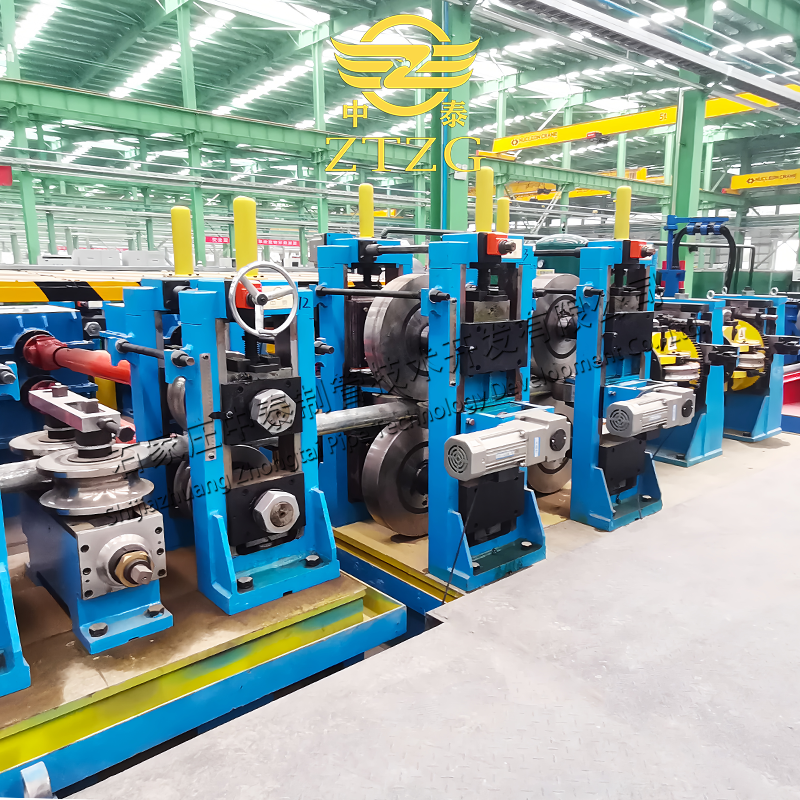
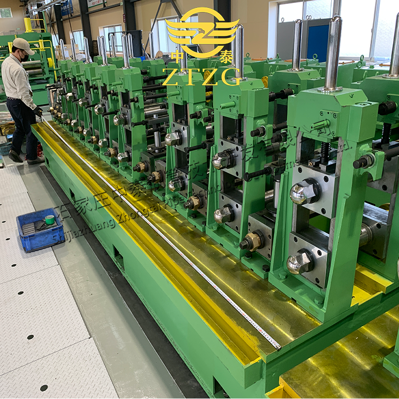
In the previous installment, we covered the essential steps of uncrating, inspecting, hoisting, and performing the rough adjustments on your new ERW tube making machine. Now, we move on to the critical process of precise alignment and adjustment, a key factor in ensuring high-quality tube production and efficient operation.
Understanding Adjustment: The Goal of Perfect Alignment
Adjustment, in this context, refers to the fine-tuning of the roll forming process to ensure the tube blank runs smoothly and stably through the machine, ultimately producing tubes that meet the required specifications. If the machine can manufacture tubes this way, then it can be said that the “adjustments” have been a success. Further adjustments during regular production runs are generally best considered as “troubleshooting” when things aren’t working as expected.
The adjustment of a weld tube unit can be divided into the following steps:
I. Preparation is Key: Inspecting Rolls and Assessing Machine Condition
Before diving into the adjustment process, careful preparation is essential:
- Roll Quality Inspection: Focus on the shape of the roll forming groove. Use a template to verify that the shape of each roll conforms to the design requirements. Discard any rolls that do not meet the standards. Also, pay attention to the base diameter of the roll. This ensures all rolls rotate in sync. Matched pairs of rolls need to be equal in size and shape.
- Machine Condition Check: Ensure the machine is in optimal working order. This can be summarized as follows:
- Horizontal axes must be level.
- Vertical axes must be straight.
- Roll positioning must be stable.
- Sliding components must move freely and smoothly.
- Adjustments must be easy to make.
If the machine doesn’t meet these requirements, conduct maintenance to restore it to its basic performance capabilities. It is important to fix anything exhibiting the following behavior: unable to adjust, unstable after adjustment, or drifting position.
II. Precise Alignment: The Foundation of Quality Tube Production
1. Groove Alignment
Groove alignment is the first step in the adjustment process.
- Select a 0.5mm steel wire. Use it with the feed-in rollers of the forming machine to the straightening rollers of the sizing machine as the base length.
- Determine the center of the roll line. Secure the steel wire and set it up as a perfectly straight and static line.
- Ensure the height of the steel wire is slightly higher than the bottom diameter of the flat roller (2mm or more). That way it will avoid contact with the arc of the groove that would affect proper measurement and positioning. This steel wire will be the reference line for groove alignment.

2. Horizontal Roller Alignment
There are two methods for alignment horizontal rolls:
- Method 1: Utilize the adjustment motor to compensate for the thickness differences between the various groove rollers. However, if the parts processing accuracy does not meet the requirements, cumulative errors can easily occur after assembly, directly affecting the alignment effect of the roll shapes.
- Method 2: Use a lock nut to adjust the position of the rollers on the shaft, so that the center of the groove of each roller can coincide with the center line. A special template is used to check the positioning of the groove center. When checking, put the template into the groove being aligned, and then slowly lift the upper end. When the steel wire can smoothly fall into the center groove of the template, it indicates that the center position of the groove is correct, otherwise, axial movement adjustment is required. This is a relatively simple alignment method.
Aligning the upper rollers uses the bottom rollers as a reference. After calculating the center distance between the upper and lower flat rollers, adjust the upper rollers to a horizontal position. The formula for calculating the axial center distance is as follows:
- Open Groove Axial Center Distance Calculation: H = (Dlower + Dupper) ÷ 2 + t – a
- Closed Groove Axial Center Distance Calculation: H = Dlower + 2R – aWhere:
- Dlower = Bottom diameter of the lower roller (mm)
- Dupper = Outer diameter of the upper roller (mm)
- t = Tube blank thickness (mm)
- R = Radius of the sizing groove (mm)
- a = Reduction coefficient (0.1~0.5)
The amount of coefficient a depends mainly on the thickness of the tube blank, the amount of reduction in the outer diameter of the tube, the size and specifications, and the actual situation such as the shaft diameter and the elastic deformation of the shaft. However, cold rolling cannot occur on the forming machine. Whether the amount of reduction selected is reasonable can be measured and checked by the indentation marks of the fuse wire. When sampling, first start the unit and open it to the slowest speed, then bend the fuse wire whose diameter is slightly larger than the thickness of the tube blank to roughly match the groove, and slowly feed it into the rolling mill to obtain the fuse wire’s indentation.
After the upper roller is leveled, the axial center position of the upper roller of the open groove can also be centered with a template-style plug gauge to check whether the gap between the two sides of the lower roller groove and the upper roller groove is the same. If they are the same, the axial position of the upper roller can be locked. Use the touch method for closed grooves to check whether the upper and lower grooves fit together.
3. Vertical Roller Alignment
Vertical roller alignment can be divided into three steps:
- First, determine the opening gap of each group of vertical rollers, that is, the axial center distance between the two vertical rollers;
- Then, find the center position of each group of vertical rollers;
- Finally, adjust the height of the vertical rollers.
The opening gap of the vertical roller should be based on the deformation opening width during the roll shape design, and then shrink by about 5mm. If the amount of shrinkage is too large, it will accelerate the wear of the upper edge of the vertical roller roll shape and increase the load on the equipment.
The center of the vertical roller should be aligned at the same time as the horizontal roller to ensure that the center positions of the horizontal and vertical rollers are on the same center line. After the center line of the vertical roller groove is found, the steel wire can be lowered to the bottom diameter position of the horizontal roller groove, and the height of the vertical roller can be started. The height of the vertical roller should be based on the height of the lower edge of the vertical roller groove matching the height of the steel wire. The height of the first few vertical rollers before forming should be determined according to the process parameters of the amount of ring cutting of the lower roller.
4. Other Groove Alignments
The alignment method of other roll shapes can refer to the alignment principle of flat rollers and vertical rollers. It’s just that the bottom diameter position of the lower roller of the guide roller should be slightly higher than the reference line by 0.5~2 mm (depending on the diameter and wall thickness of the produced tube). The burr support roller should be 0.5mm higher than the reference line to make the force more stable when planing the outer burrs and prevent planing from jumping.
Post time: Feb-11-2025


